Hydraulic impact or surge, appears in pipelines during the moving circulation of liquid and it is caused by sudden exchange of circulation speed (due to operation interruptions caused by power failure, sudden closing of Valve etc). The impact is followed by intensive pressure oscillations, with strong loud gusts, which often lead to failure of an entire pipeline network or some of its components.
Apart from timed valves being used, as well as different clamps, pump flywheels etc, pipelines and equipments can also be effectively protected from hydraulic impact if membrane compensation vessels are used, in this case marked as "PUP vessels“.
Application
PUP vessels are used in installations for transportation of liquid fluids especially in systems that supply drinking and technical water (other fluids on request) and wherever indicated by project planning or in cases of hydraulic impact (surge). Vessels are defined according to the type of fluid
they are used for, the size, nominal pressure, required pre-filling pressure, maximal and minimal pressures that occur during operation (with impact) and also nominal radius of the connector. PUP vessels can be installed in the open, along the pipeline route.
Mode Of Operation
PUP devices are, after being assembled and prior to the operation start, filled with gas up to the required pressure as set and indicated by the design. When the network and the system are set in operation, liquid with the pressure higher than the pre-filling pressure penetrates the vessel, raising the gas pressure to the pressure of the system.
With pumps "dropping out" of the system or when the circulation is forcibly interrupted, thus making the static pressure change into the dynamic pressure and causing recurrent power on account of geodetic height rise, the fall and the rise in pressure becomes compensated for by a vessel that decreases and increases pressure by releasing air and also by taking in a part of the liquid mass. As soon as the maximal pressure has been achieved the vessel returns the excess liquid, which it had accumulated, back into the network thus causing pressure drop in it. The initial pressure fluctuation represents the first impact oscillation that is permanently registered by the vessel manometers as maximal and minimal pressure. A series of muffled oscillations follow until the system resumes its normal functioning.
1. Pre charging
The device is formed by firstly pouring ballast water between membrane and vessel wall. Ballast water is needed to alleviate friction of the membrane and walls of the vessel. The air is then pumped into the space between the membrane and the wall of the vessel, and thereby all the air from membrane is pumped out. The air is pumped in until the projected pre-charge is reached. With this product is ready for connection to the pipeline.
2. Steady state
When the gate valve on the connection pipe is opened working fluid fills membrane to the static pressure of the pipeline. Static pressure is always higher than pre-charge pressure, therefore static pressure is compressing pre-charge pressure until pressure from the network and the vessel become equal. At this state the membrane is filled with working fluid to about 50% by volume of the container.
3. Operating state
The inclusion of pumps increases the pressure in the pipeline and in the vessel itself, which is at that time fulfilled about 70% by volume. This level of fulfilment stays until pumps shut down.
4. Pressure drop
When pumps stop operating, drop in pressure and fulfilment of working fluid in membrane occurs. Air pressure, that is situated in the space between the membrane and the wall of the vessel, pushes the working fluid into the network (pipeline), to avoid disruption of the water column, until the point where the force of gravity redirect the flow in the opposite direction and fluid move back.
5. Wave
Returning working fluid is charging membrane until the air pressure, that is situated in the space between the membrane and the wall of the vessel, stops it. Also now the air pressure, that is situated in the space between the membrane and the wall of the vessel, pushes the working fluid back to the network (pipeline). A few oscillations of the membrane occurs until the final settling to the static pressure.
6. Steady state
The device is ready for a new cycle of pumps inclusion.
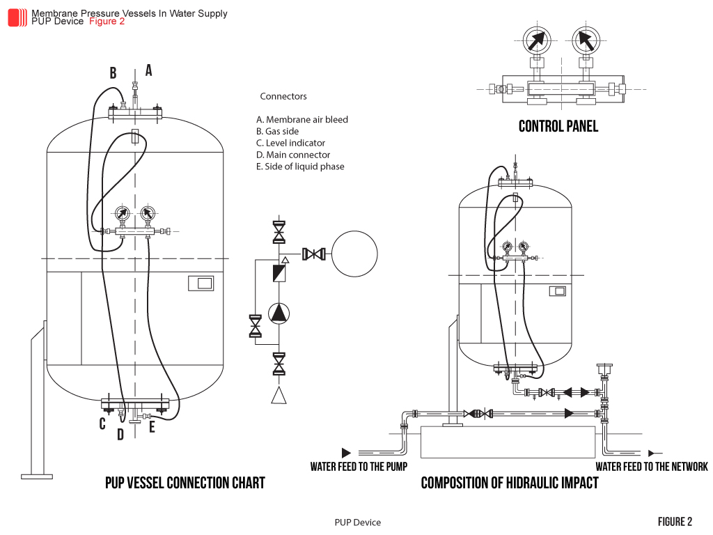
Vessel Equipment
The vessel contains a connecting gate through which the vessel is being filled and refilled with air, control panel with manometers, reinforced hoses used for connecting the panel to the vessel and water indicator for control of the water level in the membrane. If required the vessel can get an automatic level control installed which, if necessary, can block the pumps operation. Connecting mode is described in figure 2.
Choice Of Equipment
The choice of size and nominal parameters for these counter impact devices is determined solely through a project analyses for a particular network, its part and configuration.
General Advantages And Benefits
By using PUP devices following advantages and benefits are:
– does not require additional external energy,
– can be installed indoors, outdoors and anywhere where local protection against water hammer
is needed,
– maintenance costs are minimal,
– container does not allow interruption the water line (vacuum pipeline),
– membrane is interchangeable,
– longer lifetime in service.